The AYI-G14 Yagui antenna 806-960 MHz 14 dBi – Yagui AYI-G14 directive antenna from 800 to 960 MHz with N female connector and 14 dBi gain is a commercial-grade, fixed-station directional radiator precision-engineered to deliver secure voice synchronization, high-integrity spatial frequency tracking, and reliable point-to-point data links across cellular, utility, and industrial telecommunication sectors. Designed to overhaul weak omnidirectional antennas that suffer from signal splitting and local signal path degradation, this premium multi-element array concentrates RF energy into a tight, high-intensity forward path. It stands as an essential operational procurement asset for wireless local loop extensions, SCADA telemetry hubs, regional signal booster arrays, and high-volume B2B radiocommunication hardware wholesale distribution networks looking to source authentic factory-engineered directional antenna lines.
The advanced internal RF architecture of this high-compliance hardware element is strictly optimized to operate within a continuous frequency range 806~960 MHz. This targeted tuning ensures an exceptionally low voltage standing wave ratio (VSWR) across critical industrial and utility telemetry blocks, protecting internal transmitter power amplifiers from destructive reverse-power thermal accumulation during continuous duty cycles. By delivering a concentrated gain 14 dBi performance curve focused directly along a uniform polarization vertical orientation, it maximizes fringe-area line-of-sight path propagation and signal clarity over complex field environments, heavy tree cover, and remote concrete facilities.
Spatial radiation efficiency is carefully governed by its symmetric beamwidth geometry, clocking a highly directive half power beamwidth H-plane 30°, e-plane 30° mapping block. This focused horizontal and vertical angle intercept limits unwanted side-lobe crosstalk reception, filtering out ambient multi-path electromagnetic interference (EMI) from neighboring channel coordinates. Constructed to survive demanding multi-season environmental deployment schedules, the robust structural chassis measures a physical element height 930 mm and terminates in a premium, weatherized N female connector port with heavy-duty threading to achieve a moisture-resistant mechanical seal against transmission line drop leads and guarantee absolute field deployment readiness.
Technical Specifications
| Technical Parameter | Specification |
|---|---|
| Product Brand Designation | Yagi (Original Factory Genuine Electronics Infrastructure Line) |
| Hardware Model Designation | AYI-G14 High-Gain Directional Matrix |
| Primary Component Classification | Multi-Element Directional Yagi Base Station Antenna Array |
| Active Operational Bandwidth | Continuous 806 MHz to 960 MHz UHF Frequency Band Pass Matrix |
| System Active Radiation Gain | 14 dBi High-Efficiency Directional Forward Power Curve |
| Antenna Polarization standard | Vertical Wavefront Field Alignment |
| Half-Power Beamwidth (HPBW) | • H-Plane (Horizontal Sector): 30 Degrees Focused Aperture • E-Plane (Vertical Sector): 30 Degrees Focused Aperture |
| System Characteristic Impedance | 50 Ohm Nominal RF Link Standardization Profile |
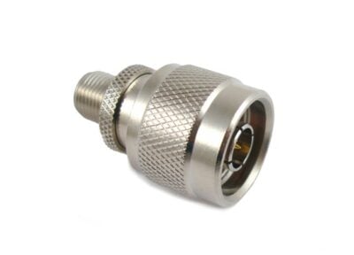
| Primary Base Connection RF Port | N-Type Female Heavy-Duty Threaded Coaxial Chassis Socket |
| Total Measured Boom Length | 930 mm Mechanical Height Clearance Footprint |
| Chassis Structure Assembly | Corrosion-Resistant Heavy-Duty Aluminum Alloy with Weatherized Dipole Box |
| Verified Hardware Compatibility Scope | N-male terminated low-loss LMR-400/RG-213 coaxial cables, cellular repeater modules, SCADA tracking transceivers, wireless telemetry gates, and heavy-duty steel utility masts |
| Primary Fleet Utility Purpose | Turnkey command base outfitting, directional long-range link propagation, cross-channel signal tracking stabilization, and transmitter output circuit protection |