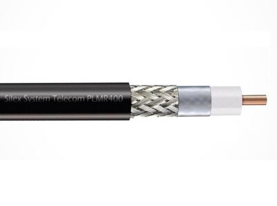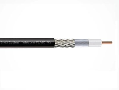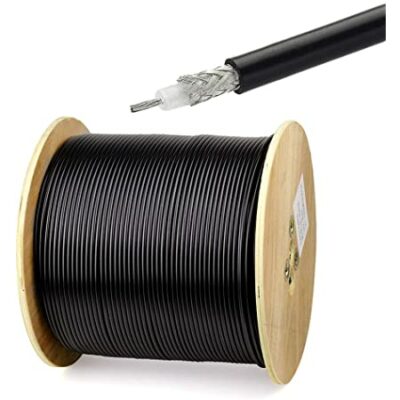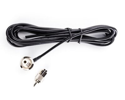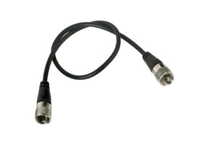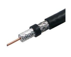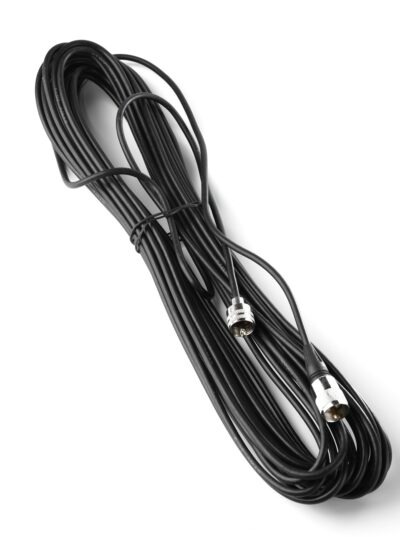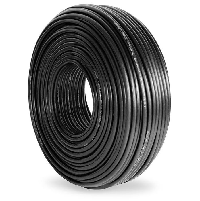
The RG-213 coaxial cable (100 m coil)-The RG-213 is a coaxial cable with 50 Ω for radio frequency, made with polyethylene insulation, shielding based on braided copper wires, and PVC jacket. Based on the MIL-DTL-17/74 C standard. is a commercial-grade, military-spec transmission line precision-engineered to deliver secure voice synchronization, ultra-low-loss power distribution, and complete circuit line conditioning across high-power transceiver grids. Manufactured to satisfy rigid global standards, this heavy-duty transmission fluid medium overhauls standard thin-diameter patches that cause massive attenuation losses and heat accumulation under dense RF loads. It stands as an essential operational procurement asset for commercial maritime communication bridges, industrial utility base tower rigging, public emergency dispatch arrays, and high-volume B2B radiocommunication accessory wholesale distribution networks requiring factory-certified bulk cable runs.
The core electrical architecture of this high-compliance 50-ohm cable relies on a premium conductor: polished copper 7×0.72 mm s/MIL-DTL-17 core configuration. This stranded internal wire core delivers excellent physical flexibility while optimizing skin-effect conductivity across an expansive spectrum up to a designated maximum working frequency: 1,000 MHz baseline. Telemetry metrics show an ultra-efficient internal structure with a nominal characteristic impedance: 50 ± 2 Ω link rating, an exceptionally tight capacitance: < 100 pF/m threshold, a balanced propagation speed: 66% velocity factor, and a minimal electrical resistance of the inner conductor: < 5.8 Ω/km, allowing long-distance horizontal and vertical cable routing without degrading critical fringe signals.
To guard weak radio vectors against heavy ambient electromagnetic interference (EMI) and cross-channel industrial noise, the cable is wrapped in a high-density suppression envelope. It incorporates a specialized insulation: BDPE polyethylene s/MIL-DTL-17 dielectric separator measuring a structured Ø over insulation: 7.25 mm s/MIL-DTL-17, surrounded immediately by a heavy-duty shield: braided polished copper wires s/MIL-DTL-17 layer achieving an elite physical coverage: > 95.3 % s/MIL-DTL-17. This dual-layer containment prevents signal leaking and cross-channel bleed while maintaining low attenuation ratings across standard operation matrices, recording a typical attenuation of < 3.9 dB/100 m at 50 MHz, < 7.5 dB/100 m at 100 MHz, < 15.7 dB/100 m at 400 MHz, and < 29.5 dB/100 m at 1,000 MHz.
Built to survive demanding environmental stress lines, toxic chemical runoff, and severe multi-season weather fatigue, the external assembly features a robust outer jacket: TM52 PVC s/UNE-EN 50290 protective layer finished in a standard UV-stabilized usual color: black. The finished profile holds a sturdy outer diameter: 10.3 ± 0.20 mm s/MIL-DTL-17 clearance framework and passes strict industrial safety tests, passing a high Spark Tester voltage (V r.m.s.): 5,000 V factory isolation stress screening. Shipped as a continuous turnkey deployment resource on a high-volume 100-meter bulk storage spool, this heavy-duty coaxial line ensures absolute out-of-the-box field readiness for your communications grid installation pipeline.
Technical Specifications
| Technical Parameter | Specification |
|---|---|
| Product Distribution Format | 100-Meter (100 m) Continuous Bulk Storage Coil Spool |
| Hardware Model Designation | RG-213 / RG213 Military Specification Series |
| Primary Component Classification | Low-Loss Heavy-Duty Solid Radio Frequency Coaxial Transmission Cable |
| Engineering Production standard | MIL-DTL-17/74 C High-Compliance Military Quality Baseline |
| System Characteristic Impedance | 50 Ohms Nominal (Strict ± 2 Ω Matching Impedance Tolerance) |
| Maximum Active Working Frequency | 1,000 MHz (1.0 GHz) Continuous Band Pass Spectrum Limit |
| RF Signal Path Attenuation Curve | • HF Band Pass (50 MHz): Less than 3.9 dB per 100 meters • VHF Band Pass (100 MHz): Less than 7.5 dB per 100 meters • UHF Band Pass (400 MHz): Less than 15.7 dB per 100 meters • SHF Band Pass (1,000 MHz): Less than 29.5 dB per 100 meters |
| Conductor Metal Structure Core | 7 Strands × 0.72 mm Geometry Polished Pure Copper s/MIL-DTL-17 |
| Internal Dielectric Insulation | BDPE Polyethylene Solid Extrusion Matrix (7.25 mm Outer Diameter) s/MIL-DTL-17 |
| Active Screen Shield Intercept | Braided Polished Copper Wire Matrix with Greater than 95.3% Total Physical Coverage |
| System Operational Velocity Factor | 66% Constant Signal Propagation Speed Rating |
| Core Capacitance Specification | Less than 100 pF/m (Picofarads per meter) Linear Dispersion Limit |
| Inner Conductor DC Resistance | Less than 5.8 Ohms per kilometer (< 5.8 Ω/km) Total Line Resistance |
| Factory Spark Tester isolation | 5,000 V (Volts Root Mean Square) Dielectric Breakdown Withstand Limit |
| External Sheath Insulation jacket | TM52 Heavy-Duty Weatherized Polyvinyl Chloride (PVC) s/UNE-EN 50290 |
| Total Physical Outer Diameter | 10.3 mm (Strict ± 0.20 mm Dimensional Tolerance) s/MIL-DTL-17 |
| Chassis Sheath Color Profile | UV-Stabilized Non-Contaminating Industrial Matte Black |
| Verified Hardware Compatibility Scope | PL-259 male solder/crimp fittings, N-Type high-retention male plugs, base station duplexers, high-power linear amplifiers, directional yagi arrays, and antenna switches |
| Primary Fleet Utility Purpose | Turnkey antenna tower outfitting, high-power transmission tracking stabilization, RF infrastructure line conditioning, and receiver front-end bleeding protection |