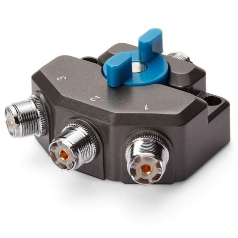

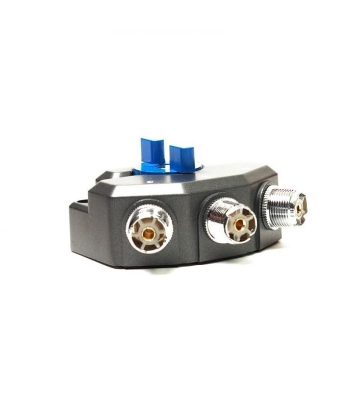
The Avair AV-SW3M Antenna Switch (3 ports) – The Avair AV-SW3M is a 3-port antenna switch with PL connector. is a commercial-grade, high-isolation coaxial distribution matrix precision-engineered to deliver secure voice synchronization, flexible multi-path spectrum tracking, and complete circuit front-end protection across multi-frequency stations. Built to overhaul cumbersome layout changes that require manual cable detachment, this premium hardware selector allows command hubs to route up to three individual transmission lines cleanly to a single transceiver output. It stands as an essential operational procurement asset for commercial maritime communication networks, tactical public safety bases, emergency response dispatch arrays, and high-volume B2B radiocommunication infrastructure hardware accessory wholesale distribution channels looking to source original factory-genuine RF management gear.
The advanced internal RF architecture of the AV-SW3M is optimized to manage an expansive, continuous operational frequency bandwidth stretching over a frequency range: up to 3000MHz. Engineered to maintain strict structural path integrity, it accommodates heavy-duty transmit power scales through a frequency-tiered maximum power configuration matrix. The system safely conditions a maximun power up to 30 MHz: 1.5kW, scales to 1.0 kW across 30 – 200 MHz, drops to 500W across 200 – 500 MHz, and comfortably sustains 250W across 500 MHz – 800MHz. This flexible threshold protection safeguards delicate external antenna loads and internal radio circuit segments from overheating or power reflection blocks during intense shift operations.
To preserve the absolute baseline signal strengths required for deep-fringe tracking, the internal mechanical cavity features ultra-low attenuation tolerances. It guarantees a minimal insertion loss up to 500 MHz: ≤0.05 dB and ≤0.1dB from 500MHz – 800MHz, preventing signal degradation across long-distance communication lines. Concurrently, the mechanical framework provides excellent crosstalk shield isolation, clocking an isolation up to 500 MHz: ≥70 dB and ≥60dB from 500MHz – 800MHz, effectively muting stray RF bleed from unselected channels. This system maintains an exceptional SWR up to 500 MHz: ≤1.15 and ≤1.25 from 500MHz – 800MHz, ensuring standard transmission grids stay protected from impedance matching drops.
Housed inside a heavy-duty, cast metal alloy shield enclosure that dampens ambient electromagnetic interference (EMI), this switch layout features a convenient number of ports: 3 distribution configuration. The interface connections feature high-retention threaded fittings, including a dedicated input connector: PL female (SO239) base port linked cleanly to a corresponding triple output connector: PL female (SO239) configuration. Delivering an absolute turnkey solution for complex multi-band multi-antenna setups requiring quick, manual frequency routing switches without introducing system matching faults, this high-power antenna selector delivers out-of-the-box field deployment readiness.
Technical Specifications
| Technical Parameter | Specification |
|---|---|
| Product Brand Designation | Avair (Original Factory Genuine High-Tier RF Distribution Line) |
| Hardware Model Designation | AV-SW3M High-Power Coaxial Switch |
| Primary Component Classification | Manual 3-Way Heavy-Duty Coaxial Antenna Selector Switch Matrix |
| Total Configured Output Lines | 3 Operational Output Switch Ports |
| Active Operational Bandwidth | Continuous DC up to 3000 MHz (3.0 GHz) Wideband Tracking Range |
| RF Transmission Power Handling | • HF Band (Up to 30 MHz): 1.5 kW (1500W) • VHF Band (30 – 200 MHz): 1.0 kW (1000W) • UHF Band (200 – 500 MHz): 500 Watts • SHF Segment (500 – 800 MHz): 250 Watts Maximum Nominal Capacity |
| RF Signal Path Insertion Loss | • Up to 500 MHz: Less than or equal to 0.05 dB • 500 MHz to 800 MHz: Less than or equal to 0.1 dB |
| Cross-Channel Isolation Attenuation | • Up to 500 MHz: Greater than or equal to 70 dB • 500 MHz to 800 MHz: Greater than or equal to 60 dB Shield Intercept |
| Voltage Standing Wave Ratio (VSWR) | • Up to 500 MHz: Less than or equal to 1.15 • 500 MHz to 800 MHz: Less than or equal to 1.25 Matching Target |
| System Characteristic Impedance | 50 Ohm Nominal Interconnect Standardization Profile |
| Primary Input Hardware Interface | 1x PL Female (SO-239 Heavy-Duty Threaded Socket Core) |
| Primary Output Hardware Interfaces | 3x PL Female (SO-239 Heavy-Duty Threaded Socket Distribution Points) |
| Mechanical Control Layout | Manual Rotary Click-Stop Detent Lever with Instant Path Lock |
| Verified Hardware Compatibility Scope | HF/VHF/UHF multi-band base transceivers, PL-259 terminated RG-58/RG-213 coaxial leads, directional yagi arrays, multi-band vertical base whips, and test benches |
| Primary Fleet Utility Purpose | Turnkey multi-antenna command base outfitting, real-time manual line tracking, transmission loop isolation, and receiver front-end surge safety |