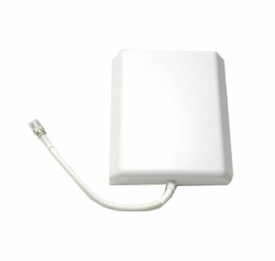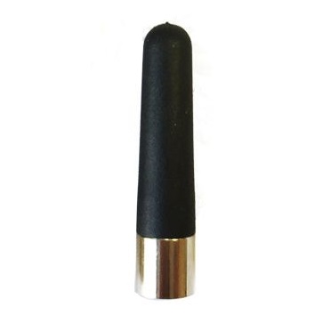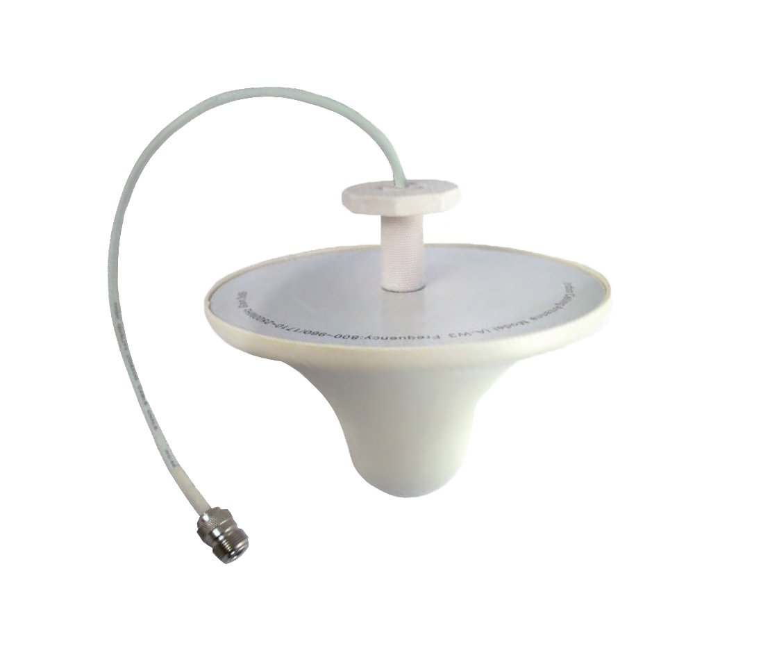
The IA-W3 professional indoor omnidirectional roof antenna is a commercial-grade, low-profile signal distribution element engineered to provide uniform, 360-degree wireless coverage within modern interior environments. Utilizing a specialized dome architectural framework often referred to as a “lapa type” layout, this high-integrity antenna is designed for flush ceiling installation to blend seamlessly into corporate offices, commercial centers, and industrial facilities. It functions as an essential, high-performance network node for cellular repeaters, distributed antenna systems (DAS), and wireless telecommunication infrastructures across European distribution networks.
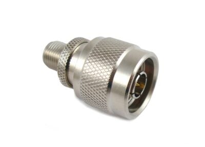
The ultra-wideband electrical engineering of the IA-W3 offers universal compatibility across all major network operators and multi-protocol infrastructures, operating efficiently through a broad 800 MHz to 2,500 MHz frequency range. This expansive bandwidth delivers native support for CDMA, iDEN, GSM, DCS, PCS, UMTS, and 2.4GHz Wi-Fi applications. As clearly illustrated in the product presentation within the file image_df5b02.png, the antenna features an integrated low-loss pigtail cable feedline passing through a threaded central mounting stem, complete with a tightening nut for structural ceiling stability. The internal radiation matrix is vertically polarized, maintaining a strict VSWR of 2.0:1 or less across the spectrum. It delivers a calibrated 2dBi gain metric from 800 to 960 MHz and scales up to a 3dBi gain from 1,700 to 2,500 MHz. While configured for a standard 50 Ω nominal impedance, it can adapt to 75 Ω distribution systems using a specialized N-F RF adapter, ensuring immediate system alignment and fleet deployment readiness.
| Technical Specification Parameter | Value & Fleet Alignment Matrix |
|---|---|
| Hardware Model Designation | IA-W3 |
| Primary Component Classification | Indoor Omnidirectional Roof Mount Dome Antenna (“Lapa” Type) |
| Operational Frequency Bandwidth | 800 MHz to 2,500 MHz Continuous Wideband Coverage |
| Verified Protocol Interoperability Scope | CDMA, iDEN, GSM, DCS, PCS, UMTS (3G), and 2.4GHz Wi-Fi Networks |
| Antenna Radiation Gain Matrix | 2dBi (800–960 MHz) / 3dBi (1,700–2,500 MHz) High-Aperture Output |
| Voltage Standing Wave Ratio (VSWR) | Less than or equal to 2.0:1 across entire operational envelope |
| Antenna Radiation Polarization | Vertical Polarization Mode |
| System Characteristic Impedance | 50 Ohms Nominal (Adaptable to 75 Ohms via external N-F RF adapter) |
| Cable Lead Assembly Type | Integrated low-attenuation pigtail wire with chassis strain relief (per image_df5b02.png) |
| Physical Dimensions & Profile | 16.5 x 12.5 cm Low-Profile Interior Silhouette |